Trailer Brake Wiring Diagram 7 Way / Wiring Diagrams Towing Centres Uk Ltd : Variety of trailer breakaway wiring schematic.
Dapatkan link
Facebook
X
Pinterest
Email
Aplikasi Lainnya
Trailer Brake Wiring Diagram 7 Way / Wiring Diagrams Towing Centres Uk Ltd : Variety of trailer breakaway wiring schematic.. This trailer wiring diagram 7 way with breakawayversion is far more appropriate for sophisticated trailers and rvs. Trailer wiring diagrams trailer wiring connectors. A wiring diagram is a simplified conventional photographic depiction of an electric circuit. 2001 f250 trailer brake controller wiring diagram, 2005 ford f250 factory trailer brake controller wiring diagram, 2005 ford f250 trailer brake controller wiring diagram, 2006 ford f250 trailer brake controller wiring diagram, 2008 ford f250 trailer brake controller wiring diagram, ford trailer brake controller wiring diagram 7 way trailer plug wiring diagram dodge Most of us aren't electricians, but that doesn't mean wiring a trailer or replacing corroded wiring is beyond us.
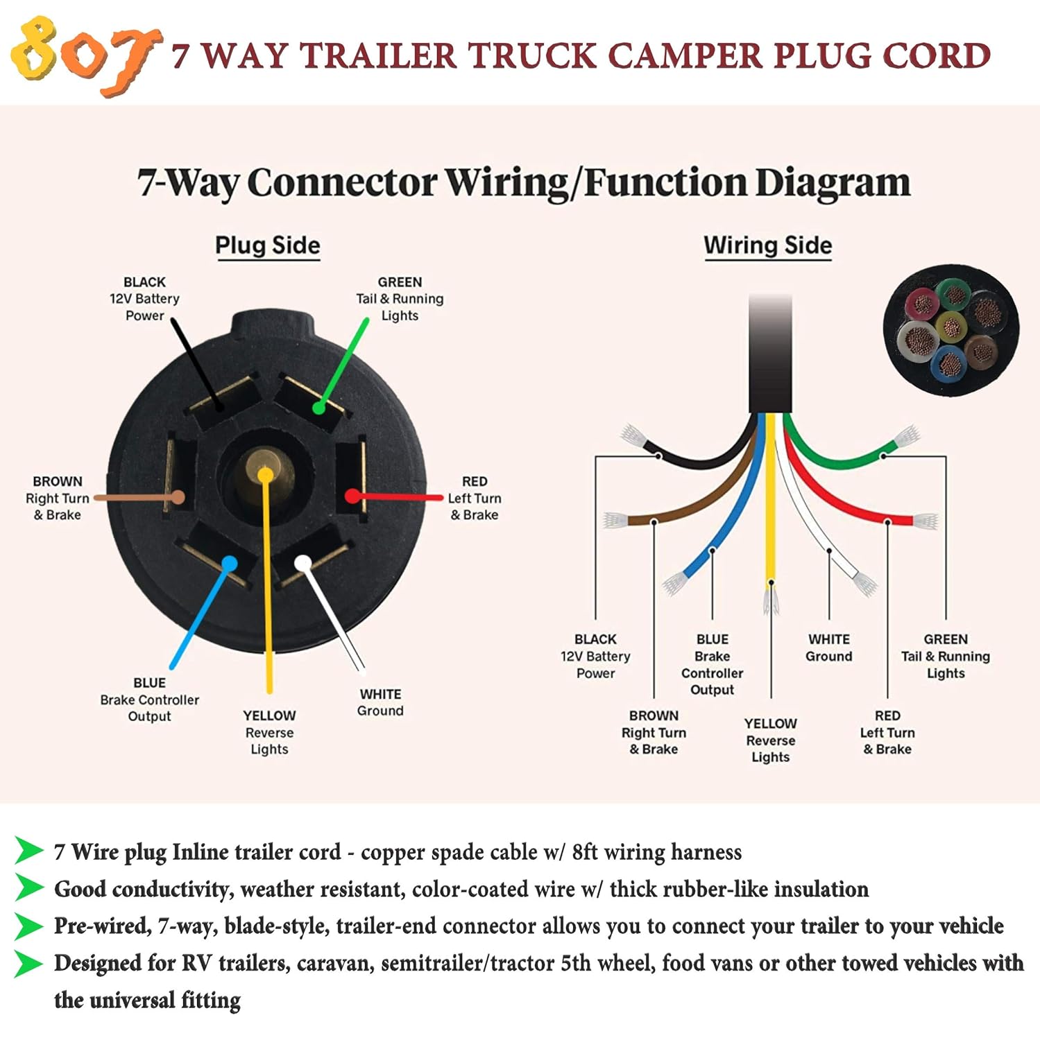
A lot of led lights come with black and white wires and people can easily confuse the black wire for the ground. Most of us aren't electricians, but that doesn't mean wiring a trailer or replacing corroded wiring is beyond us. If your vehicle is not equipped with a working trailer wiring harness, there are a number of different solutions to provide the perfect fit for your specific vehicle. The other thing that you will get a circuit diagram could be lines. Injunction of two wires is usually indicated by black dot to the junction of two lines.
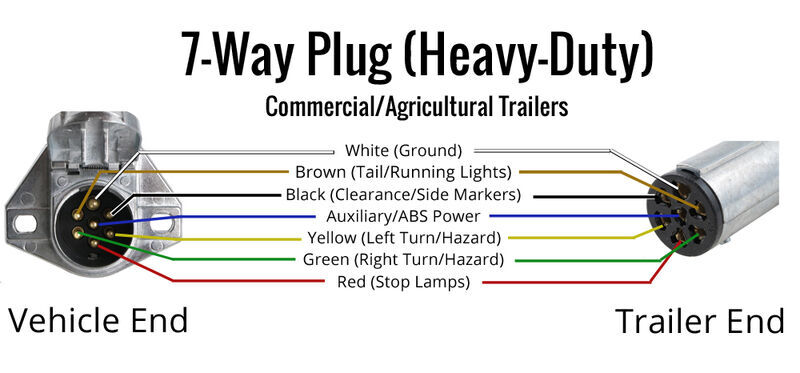
Wiring Trailer Lights With A 7 Way Plug It S Easier Than You Think Etrailer Com from www.etrailer.com A faulty and unsecured ground wire is often the. Wiring plug diagram created date: This vehicle is designed not just to travel 1 place to another but also to carry heavy loads. Variety of trailer breakaway wiring schematic. The diagrams below show the typical trailer wiring for 4 pin flat connectors all the way to 7 pin round connectors. Trailer side car side wiring plug diagram. Interlock system keeps connections in place. By law, trailer lighting must be connected into the tow vehicle's wiring system to provide trailer running lights, turn signals and brake lights.
In the trailer wiring diagram and connector application chart below, use the first 5 pins, and ignore the rest.
Interlock system keeps connections in place. This vehicle is designed not just to travel 1 place to another but also to take heavy loads. Wiring plug diagram created date: 2001 f250 trailer brake controller wiring diagram, 2005 ford f250 factory trailer brake controller wiring diagram, 2005 ford f250 trailer brake controller wiring diagram, 2006 ford f250 trailer brake controller wiring diagram, 2008 ford f250 trailer brake controller wiring diagram, ford trailer brake controller wiring diagram 7 way trailer plug wiring diagram dodge A lot of led lights come with black and white wires and people can easily confuse the black wire for the ground. It reveals the parts of the circuit as streamlined forms, as well as the power and signal connections in between the gadgets. According to previous, the lines at a trailer brake wiring diagram 7 way signifies wires. This trailer wiring diagram 7 way with breakawayversion is far more appropriate for sophisticated trailers and rvs. White pin for the ground. Trailer side car side wiring plug diagram. Return to the duplex cable under the hood, where the brake wire (now white) needs to be separated from the 12 volt hot lead (black). With such an illustrative guide, you will be able to troubleshoot, avoid, and complete your projects without difficulty. But, it does not mean connection between the wires.
Interlock system keeps connections in place. Most of us aren't electricians, but that doesn't mean wiring a trailer or replacing corroded wiring is beyond us. There are two things which are going to be present in almost any 7 pin trailer wiring diagram with brakes. The first component is symbol that indicate electrical element from the circuit. 7 way trailer connector wiring diagram
2004 F350 Trailer Brake Wiring Diagram Wiring Diagram Meet Cloud B Meet Cloud B Ristruttura4 0 It from ww2.justanswer.com White pin for the ground. Most of us aren't electricians, but that doesn't mean wiring a trailer or replacing corroded wiring is beyond us. If your vehicle is not equipped with a working trailer wiring harness, there are a number of different solutions to provide the perfect fit for your specific vehicle. But, it does not mean connection between the wires. Variety of trailer breakaway wiring schematic. There are two things which are going to be present in almost any 7 pin trailer wiring diagram with brakes. The diagrams below show the typical trailer wiring for 4 pin flat connectors all the way to 7 pin round connectors. A faulty and unsecured ground wire is often the.
11/10 for 2011 wiring diagrams note:
Trailer wiring diagrams trailer wiring connectors various connectors are available from four to seven pins that allow for the transfer of power for the lighting as well as auxiliary functions such as an electric trailer brake controller, backup lights, or a 12v power supply for a winch or interior trailer lights. The other thing that you will get a circuit diagram could be lines. This vehicle is designed not just to travel one place to another but also to carry heavy loads. Trailer side car side wiring plug diagram. A lot of led lights come with black and white wires and people can easily confuse the black wire for the ground. Let me know what you find and we can go from there. With such an illustrative guide, you will be able to troubleshoot, avoid, and complete your projects without difficulty. The diagrams below show the typical trailer wiring for 4 pin flat connectors all the way to 7 pin round connectors. It shows the components of the circuit as simplified shapes, and the capacity and signal links between the devices. Wiring plug diagram created date: If your vehicle is not equipped with a working trailer wiring harness, there are a number of different solutions to provide the perfect fit for your specific vehicle. 7 way trailer connector wiring diagram A wiring diagram is a simplified conventional photographic depiction of an electric circuit.
But, it does not mean connection between the wires. Injunction of two wires is usually indicated by black dot to the junction of two lines. Basically, it is another 12v circuit typically used for a reverse light / reverse lockout for trailer brakes. Most of us aren't electricians, but that doesn't mean wiring a trailer or replacing corroded wiring is beyond us. There are two things which are going to be present in almost any 7 pin trailer wiring diagram with brakes.
7 Pin Truck Wiring Diagram With Brake Wiring Diagram Bald Data B Bald Data B Disnar It from images-na.ssl-images-amazon.com This vehicle is designed not just to travel 1 place to another but also to take heavy loads. In the trailer wiring diagram and connector application chart below, use the first 5 pins, and ignore the rest. By law, trailer lighting must be connected into the tow vehicle's wiring system to provide trailer running lights, turn signals and brake lights. The other thing that you will get a circuit diagram could be lines. Most of us aren't electricians, but that doesn't mean wiring a trailer or replacing corroded wiring is beyond us. The diagrams below show the typical trailer wiring for 4 pin flat connectors all the way to 7 pin round connectors. Trailer side car side wiring plug diagram. Various connectors are available from four to seven pins that allow for the transfer of power for the lighting as well as auxiliary functions such as an electric trailer brake controller, backup lights, or a 12v power supply for a winch or interior trailer lights.
Interlock system keeps connections in place.
According to previous, the lines at a trailer brake wiring diagram 7 way signifies wires. The diagrams below show the typical trailer wiring for 4 pin flat connectors all the way to 7 pin round connectors. This vehicle is designed not just to travel one place to another but also to carry heavy loads. A faulty and unsecured ground wire is often the. White pin for the ground. Sometimes, the wires will cross. Trailer side car side wiring plug diagram. The other thing that you will get a circuit diagram could be lines. Assortment of electric trailer brake wiring schematic. It is supposed to help each of the average consumer in creating a correct program. A circuit is usually composed by many components. Various connectors are available from four to seven pins that allow for the transfer of power for the lighting as well as auxiliary functions such as an electric trailer brake controller, backup lights, or a 12v power supply for a winch or interior trailer lights. With such an illustrative guide, you will be able to troubleshoot, avoid, and complete your projects without difficulty.
Narrow Modern House Plans : HPM Home Plans | Home Plan: 001-3503 | Narrow lot house ... / Modern house plan to narrow lot. . These homes are made for a narrow lot design. 10% off all house plans. Modern contemporary home plan to narrow lot with three bedrooms. Enjoy and thanks for visiting. Buy my one story home plans 82 plans. A tall skinny house can become lost along the row, but that doesn't seem to be an issue with these narrow facade house ideas. Narrow lot house plan is the answer if you have a lot with only 7 to 8 meters in width. 10% off all house plans. America's best house plans feature narrow lot plans that typically offer no more than a 40' width footprint. Modern house plans are often recognized for their unique, dramatic and striking architecture. Modern Northwest - Narrow House Design ....by Studio SM ... from i.pinimg.com ...
Lampadari Moderni A Soffitto / Zqq87 moderni lampadari Plafoniera LED soffitto 85W ... / Lampada soffitto design moderno vetro satinato acciaio bianco bagno. . * un'attenta scelta di lampadari moderni a soffitto e lampade a sospensione. Vuoi rinnovare i tuoi arredi e l'illuminazione della tua casa con un lampadario moderno? News su lampade a soffitto. Lampadari moderni ikea impressionante 40 lampadari a soffitto per. Eccellente lampadari da camera bwart bianco alto potere ha condotto. Benvenuto nella sezione lampadari moderni di eprice. I lampadari moderni sono tutti predisposti per l'uso di lampadine a led , grazie agli attacchi normalizzati. Lampadari nordico, lampadario moderni a soffitto in alluminio a led per bambini lampada a sospensione a forma di cartone animato luce pendente (colore : Vasto catalogo di lampadari moderni per tutti gli ambienti della casa ✅ garanzia 5 anni, pronta consegna, ✅ 30 giorni diritto di recesso. Il lampadario da soffitt...
Starter Relay Test : How To Test A Starter Relay T X / The starter relay provides power to the starter when the key switch is turned to start. the starter relay acts like an electrical switch routing battery voltage to the starter when it receives a signal from the key switch. . One is the 12 volt positive (top) that comes from the battery. A mechanical check to see if the starter pinion gear. Step 1 inspect the battery and starter terminals. Before replacing it by a new start relay, do the test to discover if it really is the part which has a problem. If you need any too. The magnetic switch should engage and the multitester should read infinity. We also included information about the signs of a bad starter relay, how to test it, and how to replace or fix a bad one. Read on to learn more. In it, you will find all there is to know about the starter relay: If not ok, repair the open circuit to the fuse in the pdc as required. ...


Komentar
Posting Komentar